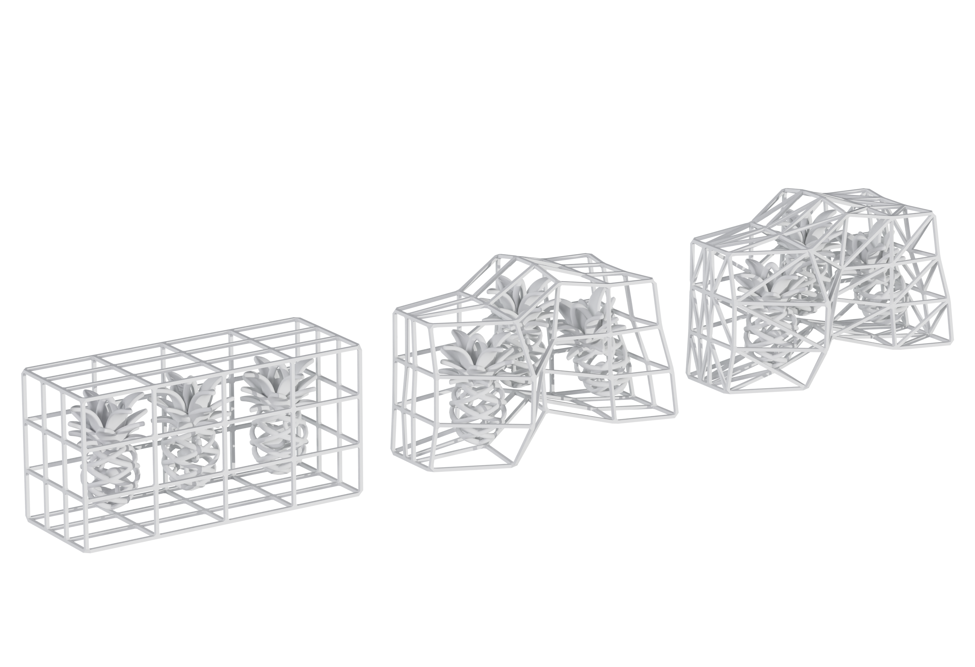
How to create a Sinterbox for 3D Printing

As I mentioned in my presentation about “ Successful design for 3D printing , SLS technology uses the material as powder (as well as MJF technology for example) and this allows us to design freeform and complex parts because support structures are not needed. This implies that the parts end up in the building bin as if they were buried in the sand. To facilitate handling and protection of small parts during the post-processing, Sinterboxes, a cage-like form, are 3D printed around them. 

In this article, I will show you how to create those Sinterboxes for 3D Printing in under one minute with the free and open-source tool Blender 3D.

Creating a Sinterbox for  Additive Manufacturing

3D Design of a Sinterbox

1. Scale it and be aware of the printing distance

First of all, you need to create a 3D cube. Scale it and adapt it to the parts you want to keep inside. 

You have to take into account the guidelines of how to design for this technology and try to make the box at least 3 – 5 mm apart from the parts inside it. To be able to see it properly, activate the “ Viewport Shading “ and the „Toggle x-Ray“.

2. Create the bars of the sinterbox

Once you have adapted the box, you need to create the rows and columns. We are going to use the „Loop Subdivide„. By pressing Ctrl + R over the box, the subdivided lines will be shown. If you scroll your mouse wheel you can create more or fewer lines. Once you decide the quantity, left-click and move the lines where you want to position them. In case you want them in the center, press right-click. Do the same for all the axis of the box. 

3. Apply Scale

Applying scale resets the values of the object’s scale to 1, while visually keeping the object data in-place. In other words, the current scale will be considered to be the “default scale”. This helps when you add a modifier because they will be calculated depending on the scale the part has.

4. Apply Skin Modifier

In order to add thickness to the structure created, we use the „Skin Modifier„. This feature uses vertices and edges to create a skinned surface, using a per-vertex radius to better define the shape.
We have to take into account giving at least 0.75mm thickness to our sinterbox to be able to have a good resistant result.

If you want to move the rows and columns, you can always go to Edit Mode and select the row or column pressing „Alt“ and Left-Mouse and afterwards „G“ twice for moving along the shape of the box.

5. Freeform Box Design

In case you want to do the Sinterbox around more irregular parts, you can always adjust it in „Edit mode“ with the „Proportional Editing“ feature selected.

6. Triangulate Modifier

Once you finished the Sinterbox, if you want more connections to make it more resistant or make the holes smaller, you can always apply the „Triangulate Modifier“ above the „Skin Modifier“.

I hope this quick overview on how to create a 3D Sinterbox is helpful for you. Please feel free to comment or send me your creations and ask me any questions!

Sign up to stay up to date about the newest tricks in

Design for Additive Manufacturing.

V

[ABTM id=2505]

Kommentare

Schreibe einen Kommentar

Deine E-Mail-Adresse wird nicht veröffentlicht. Erforderliche Felder sind mit * markiert

Diese Website verwendet Akismet, um Spam zu reduzieren. Erfahre mehr darüber, wie deine Kommentardaten verarbeitet werden.